Active cooling plays a significant role in the utilization of solar energy. In particular, the varying types of voltage and their conversion result in power loss. Under no circumstances should this lead to overheating or even the failure of the system. SEPA EUROPE has long years of experience as supplier for the renewable energy sector and supports its customers in the selection, dimensioning and know-how in all matters relating to the cooling of electronics.
The problem
Various devices suffering from power loss are doing their job between the silicon cell and the socket in order to ensure that the technical system can operate reliably and in compliance with standards. However, a well-known fact throughout virtually all the areas of electrical engineering is that complexity has increased, devices have become more compact and power density has soared. Maximum performance in a minimum of space with an efficiency that is generally known as being under 1 also means power loss. As every increase in temperature reduces the lifespan of many components involved, it is essential to implement cooling concepts that function effectively.
This gives rise to the following questions
- The costs for cooling
- The effect on the efficiency
- The lifespan of the electromechanical components (fans)
- The noise development and the maintenance intensity
The following concerns the active cooling of the devices involved and the resulting considerations. Active cooling involves the use of a fan and a heat sink.
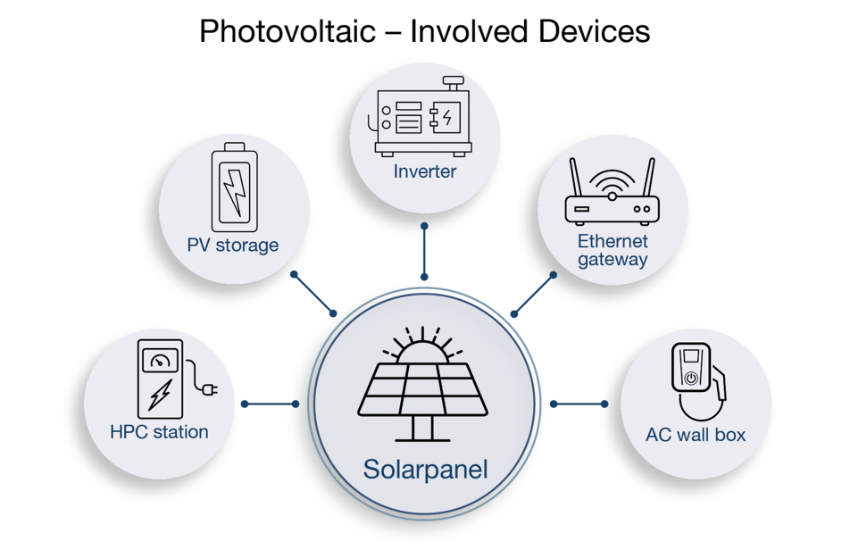
Involved devices
- 1. Solar panel
The sun shines directly on the solar panel and generates a direct current. The module does not require active cooling.
- 2. Inverter
The inverter receives the direct current from the panels and generates alternating or three-phase current via a boost converter. A large portion of the power loss is generated here and this is where the need for active cooling is at its greatest. Depending on the design 2-4 % of the AC output power needs cooling. This means 200-400 W power loss for a 10 kW converter. Roughly calculated the choice of fan can be calculated as follows without taking the housing surface into consideration:
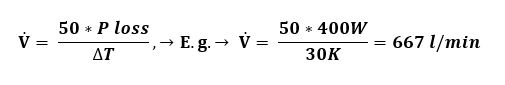
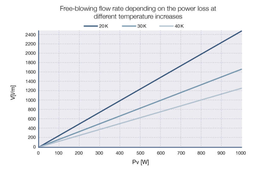
These values for power loss up to 1 kW and various increases in temperature are shown in the graphic “Devices involved”. Consideration must be given here to the fact that a component temperature that is 10K higher, halves the service life expectancy of the system. Generally speaking, it would therefore clearly be advantageous to design the cooling system more generously.
As the increase of the flow rate goes hand in hand with the noise level, active noise management should take place in the inverter (see section on noise levels).
- 3. PV storage
The photovoltaic storage for the collected electric energy does not create a significant loss of power and therefore, as is the case with the panels, it does not require active cooling. An exception to this are the storage units with integrated inverters.
- 4. Ethernet Gateway
The control and monitoring of the entire PV system are in all cases an indispensable key element. The gateway bundles and translates the communication that takes place between the components and transmits it to the operator of the PV system. In this case system-on-a-chip (SoC) processors are used that require cooling due to high transmission rates. The power loss only accounts for a few watts.
As the gateways are to some extent used in control cabinets, this is precisely where the active cooling should take place. The most suitable heat sinks are the classic ones that comprise a fan/heat sink combination that is as well-matched as possible. At the same time, it is wise to use small case fans with an edge dimension of 20 to 30 mm. These not only ensure effective heat dissipation even in situations with unfavorable thermal installation conditions or high ambient temperatures but also the long-term reliability of this central plant part.
- 5. AC Wall box
The wall box serves to charge battery electric vehicles and offers a maximum charging power of 22kW. As there is no conversion required, the power loss is low and does not require active cooling.
- 6. HPC station
A High Power Charging station has a maximum charging power of 400kW. This means that it is vital to actively cool the rectifier. Appropriate fans are powerful and equipped with a PWM input. A filter for the suctioned air is important due to the high flow rate. Suitable filters are replaceable coarse dust filters. The use of electromagnetic filters is also essential as the close meshed steel grid protects the environment against electromagnetic radiation that is emitted by the device.
Cost aspect
Heat sinks and fans that are required so that the power loss can be dissipated and the temperature restrictions of the device components can be complied with result in additional costs. The actual costs involved depend on the complexity of the design.
Efficiency
An active cooling system depends on energy consumption in order to operate and this energy is drawn from the entire system. As a consequence, the degree of efficiency drops. Thanks to the use of modern, electronically commutated DC fans this decrease in efficiency is only marginal. For example, an axial fan with 10 W power input in combination with an aluminium heat sink would be adequate to cool an inverter with an output power of 10 kW. This is equivalent to exactly one per mill.
Lifespan
Electromechanical components with bearing shafts are subject to wear and ageing. Modern bearing systems with high reliability and long lifespan increase the service life expectancy of the entire system by reducing the temperature of sensitive components (e.g. electrolytic capacitors).
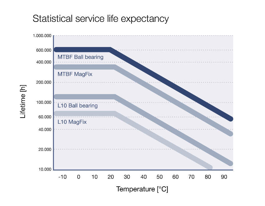
The lifespan is specified in the technical documentation of fans in L10 and in MTBF. L10 is a constructed value and defines how long it lasts until 10% of the fans of a large total quantity have failed. The basis for establishing this value are laboratory tests. These are converted to the customary operating temperatures using the Weibull distribution. The standard service life expectancy of fans is defined at 40 °C.
MTBF is the abbreviation for “Mean Time Between Failure” and provides further information on the lifespan and states when a repaired system is likely to fail again. As the fan cannot be repaired and the values are expressed for several decades, this is only of minor importance for the user. Ill 3 shows the major difference between L10 and MTBF (also MTTF) by the logarithmic scaling.
Noise level
The noise level of active cooling should be kept as low as possible particularly in systems operating in private households. This requires not only giving consideration to the sound level but also to the intelligent control of the fans via a broadband speed control. This means that between 30% and 100% of the rated speed can be set via a pulse width modulated (PWM) signal. The pulse duration in relation to the period duration is referred to as the duty cycle. Two square-wave pulses are emitted per revolution via the tacho output. The duty cycle can be adapted by evaluating this signal and in turn close the control loop. The purpose of the control is to keep the speed as high as required but as low as possible. The information on the noise level of a fan requires explanation as does its service life expectancy. The standard measurement takes place in an anechoic chamber. The fan is suspended from rubber ropes and measured at a defined distance to the fan hub (air intake side). The relevant standard is ISO 7779. This defines a distance of 1m. Small fans develop very little noise so that it is better to carry out measurement at a distance of 0.1 m. In this case the determined value is reduced by 20 dB. The results can be used for orientation purposes; however they do not represent the actual noise in an installed state. Important factors e.g. type of mounting, housing design, housing material, dynamic pressure or unfavorable flow conditions are not given consideration in the measurement. However, they do have a considerable impact on the noise of the fan. The laboratory conditions cannot be reproduced in the application and difficulties, e.g. resonance or constructions can occur that intensify the noise. These problems can be solved by decoupling, the choice of fan and the dimensions.
Maintenance intensity
Fans and heat sinks are maintenance free and require very little attention. However, fans in photovoltaic plants must be regularly checked to ensure reliable and efficient cooling. Modern fans are usually robust and highly durable, nevertheless faults or signs of wear can develop in particular in high-stress environments or where difficult conditions prevail, e.g. dust, humidity, or high temperatures. In critical systems in which a constant cooling of components is of vital importance, regular inspections and maintenance work should be carried out so that potential problems are identified and eliminated at an early stage.
Active cooling plays a significant role in the utilization of solar energy. In particular the various types of voltage and their conversion from one voltage to another produces power loss. This should not, under any circumstances, result in a system failure. SEPA Europe has many years of experience in supplying the renewable energies industry with its products and supports its customers in their choice, dimensioning and in all issues relating to the cooling of electronic components.
SEPA EUROPE GmbH develops customized cooling solutions for the electronics industry. Whether in automation technology, the automotive industry or in medical technology, the fans of SEPA EUROPE can be found wherever electronic components overheat. Thanks to a wider range of fans and accessories, SEPA EUROPE is in a position to provide fast and flexible delivery of an individualized product.