Balconies are elements which present high loads and are sensitive to bad design and execution. Additionally, they are exposed to the elements (rain, UV rays, high temperature variations, etc.) throughout their life cycle. This, added to the fact that they are not inspected afterwards, and their maintenance is impractical, makes them very susceptible areas.
It is always important to consider the design of thermal bridges in early stages of project planning, so that the solution can be integrated from the beginning to avoid redesign processes. Moreover, many of the conventional construction practices do not consider this problem and even tend to worsen it.
A frequent practice is to anchor metal beams directly to the walls or slabs. It may be thought that having less contact area between the internal and external elements will improve the thermal bridging problem, but this is not the case. In fact, making this type of anchorage without any thermal treatment leads to a concentration of the temperature flow in these areas of punctual contact, thus aggravating the problem.
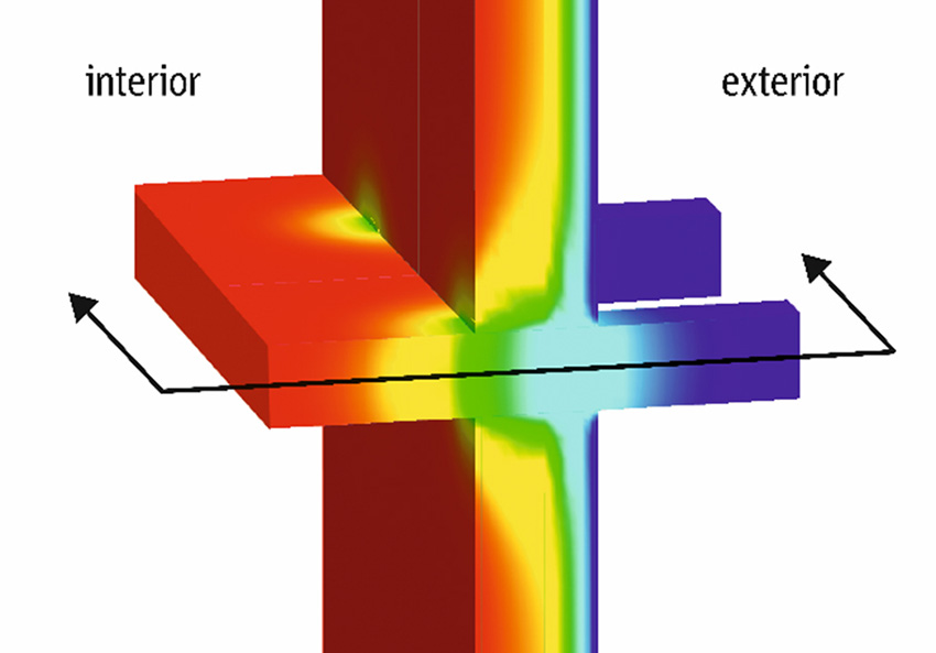
The life expectancy of a building is estimated at approximately 50 years, including the balconies. One day these beams will be so corroded by the condensation in the thermal bridge that the effective section will not be sufficient to support the loads leading to the fall of the balcony.
And when a catastrophe occurs, the question at the end is who is responsible and who is going to pay for it. These kinds of lawsuits resulting from bad design are becoming more common. That is why the conscious design of these elements is so important, since no one will inspect them, but the building designer is still responsible even years after the warranty of the building ends.
Design Process
The calculation of forces and choice of the right product is made out meticulously and with the help of modern FEM calculation software. We can summarize the process of how a thermal break system should be properly designed in 4 simple steps:
Step 1 – Structure Analysis
First check that the connection to be designed is under the following principles:
- It is not a monolithic connection (Thermal Breaks have significant difference of rigidity with rigid connections)
- It just attaches a secondary element onto the main structure (these are never part of the main structure)
- It is not part of the stability of the whole structure (no bracing forces)
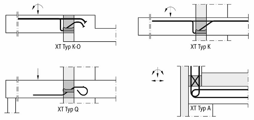
Step 2 – Pick out the right type, depending on structural situation
Next check which geometry and conditions we have:
- Is it a concrete-to-concrete, concrete-to-steel or steel-to-steel connection?
- Is the building component supported or not?
- Does the connection have a step or is the balcony at the same level as the internal slab?
- Is the building component connected to a wall or to a slab?
- Are there special conditions, such as corners or unusual slab shapes?
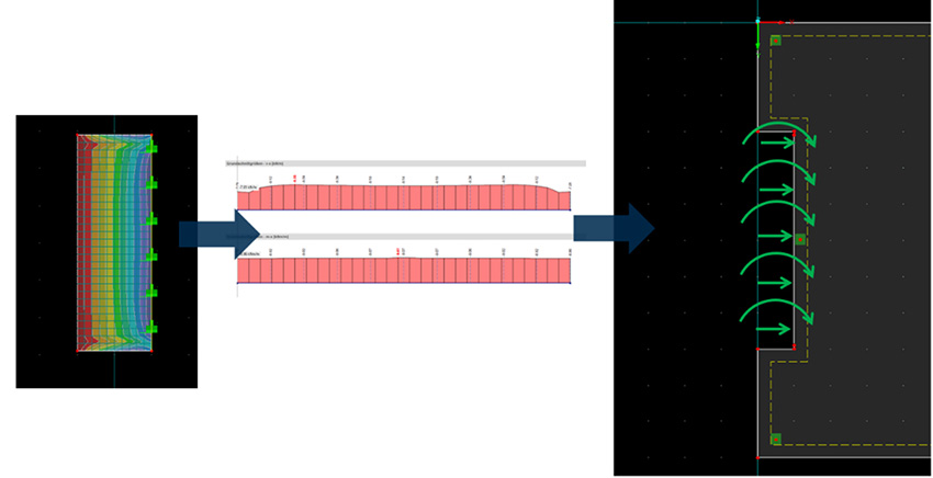
Step 3 – Load Calculation
In step 3, define all the external forces that have an impact on the connection.
- Dead loads (self-weight, finish, etc.)
- Live loads
- Environmental loads (wind, earthquake, Thermal Expansion)
In this step we use FEM software to model the balcony including all the forces involved. So, we obtain the reaction forces, apply these result forces on the edge of the slab and then we can design the slab.
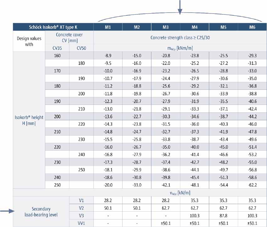
Step 4 – Pick out the right reference
Take the shear forces and moments of the connection and check in the technical manual to select the right product model. The maximum load capacity of the model selected should be above the calculated reactions.
Planning sessions and communicating information correctly are as important as getting the right result in the design. Drawings and layout diagrams of how to install products are supplied to serve as a guideline during construction so that workers know where and how to install the thermal break.
That is why it is necessary to have solutions that provide a high level of confidence and guaranty. Schöck experts offer customized solutions for any type of connection, along with full support for the projects’ thermal break needs.
Thermal expansion and contraction
As balconies and parapets are exposed to weathering, these are structures that experience slight changes in their dimensions due to temperature variations. This means that with low temperatures in winter we will have contractions and with higher temperatures such as in summer there will be expansions in these elements. And these effects must be taken into consideration in the design as well.
Limiting this thermal expansion is not realistic as the force would be enormous, so many structures have compensating joints or thermal joints. These joints allow the structure to change its geometric dimensions smoothly under temperature fluctuations, thus preventing the deterioration of the structural elements.
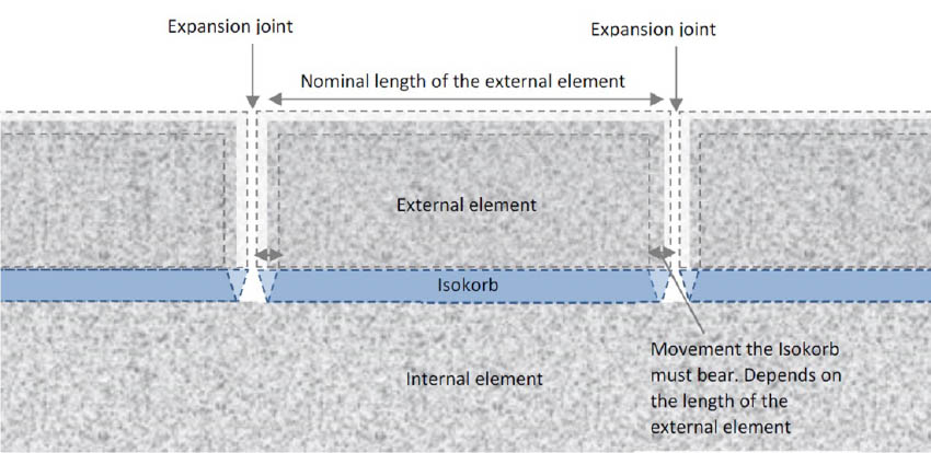
The displacements due to these expansions are small, only a few millimeters, but they have consequences on the strength of the elements, since reactions are obtained at angles different from those expected in an ideal design. That is why it is important to have a system capable of accommodating these displacements.
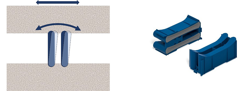
Through years of research and development, Schöck has optimized compression modules that are able to efficiently handle these lateral displacements as well as the vertical rotations caused by the loads on the y-axis of the element. The special rounded shape in both directions of the compression modules allows it to withstand the stresses successfully.
Another factor that has an important value in the integrity of the connection, is the thermal expansion stress suffered by the bars and the forces transmitted directly to the surrounding concrete.
In the steel bars we will have elongation which has a direct impact in the connection since more elongation means more stress on the fibers. We want this stress to be as low as possible and we know it is highly influenced by Young’s modulus. Schöck’s product range uses stainless steel with a very low Young’s modulus compared to other steel materials. This, plus a smaller cross-sectional area of the reinforcing element helps by giving lower levels of stress transmitted to the concrete. It’s important to reduce the danger of cracks being generated to release these forces and stresses.
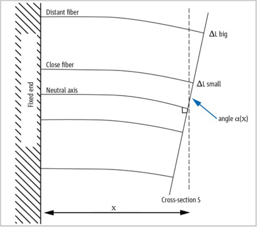
As shown, the thicker the element is in the horizontal plane, the greater the deformation of the outermost fibers and, according to Hooke’s law, the greater the load in the element.
This gives an idea of why it is beneficial to have reinforcement with smaller cross-sectional areas such as rods rather than sections such as metal plates or beams with large cross-sectional areas. Having the second case would generate a large amount of stress on the surrounding concrete which would cause many cracks in the concrete exposing the reinforcing steel and compromising the structure.
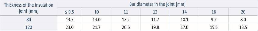
It is for this same reason that we can show how the cross section of the reinforcement is inversely proportional to the spacing allowed in the longitudinal direction of the cantilevers. Therefore, the smaller the cross-sectional area, the less stresses due to thermal expansion, which will allow us to have longer elements, however, clearly this happens in the opposite case too, the larger the cross-section of the reinforcement, the more stresses we will have, and it will be necessary to contemplate shorter elements between thermal joints so we can avoid these thermal expansion cracks, we can see an example of this in the following table:
Fatigue
This is the last effect we have on the Thermal Break system. Fatigue is the development of internal cracks and defects through time with the application of cyclic stresses which are generally lower than the yield stresses of the material. Thermal breaks are exposed to these fatigue cycles because of thermals expansions and contractions which are:
- Daily variation (day/night)
- Weather variation (warm days/cold days)
- Season variation (winter/summer)
As part of the German conformity approval process, Isokorb underwent fatigue tests in accordance with the standards. This test simulates displacement over the lifetime of the building and the resistance of Schöck Isokorb should remain constant after 20,000 cycles.
The tested and certified Isokorb product allows structural engineers and contractors to ensure the safety and reliability of their cantilevers over the years.
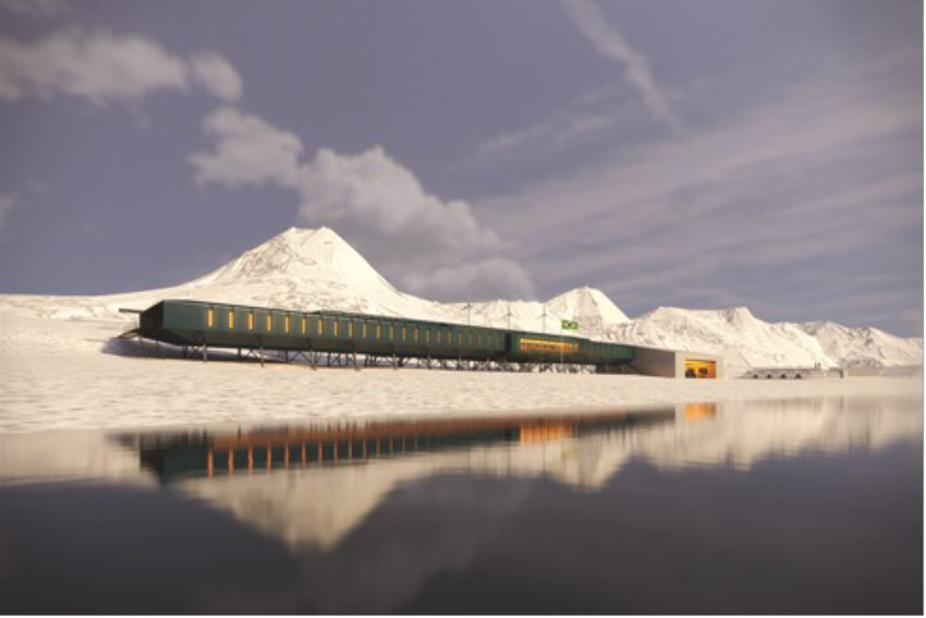
Isokorb is known worldwide for its quality and Schöck for its reliability; Schöck Isokorb is used even in most extreme temperature conditions, such as the Antarctic.